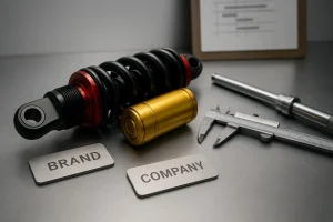


A regional aftermarket brand wants a private‑label rear shock in three colorways with laser‑engraved branding, small MOQs per variant, and a first shipment in roughly 12 weeks. This step‑by‑step case shows how we translate a rider brief into engineering targets, run rapid prototypes in parallel with tooling, assemble a PPAP‑equivalent approval package, and lock a mass‑production SOP—without compromising the feel riders notice or the visual details customers remember.
Project brief to requirements and CTQs
In Week 0–1, align on what success looks like for performance, appearance, and delivery speed. You provide platform fitment, rider profiles, target feel, and branding preferences; the supplier returns a requirements matrix and a short project plan with gates.
- What you provide: model fitment and packaging constraints; rider weight ranges and use cases; damping character targets; requested adjustability; aesthetic targets for anodize colors, engraving, and packaging; batch plan and MOQs.
- What you receive: a requirements matrix, a list of critical‑to‑quality items (CTQs), and gate acceptance criteria. For aesthetics, establish master references with visual assessment plus spectrophotometric Lab* checks and agreed ΔE bands as per the QUALANOD guidance on anodized finishes, where visual assessment remains primary with instrumented checks to support it. See the QUALANOD reference in the Appearance of Anodised Finishes guide for practical methods: QUALANOD appearance guidance.
Tip: Treat CTQs like a contract for the build. For a shock, common CTQs include stroke length, force at key velocity nodes on a dyno, torque specs on critical fasteners, oil fill and bleed parameters, engraving placement, and specified color references.
Concept, DFM, and material or finish choices
Weeks 1–3 convert the brief into concept CAD, a design‑for‑manufacturability check, and material/finish selections.
- DFM highlights: machinability and tool access for CNC features; tolerance strategy; anodizing allowances on dimensions; engraving location and fixture references; packaging protection for cosmetic parts.
- Finish choices: cosmetic components typically use sulfuric anodize with defined colorways; surfaces subject to wear may require harder finishes. Formal standards exist, but practical control relies on agreed samples, visual criteria, and ΔE targets referenced to accepted guides and standards. For fundamentals and terminology, see the Aluminum Anodizers Council overview of MIL‑A‑8625 types and classes: AAC on MIL‑A‑8625.
Risk thinking starts here. A preliminary PFMEA will usually flag color variance risks from alloy lots and thickness, engraving alignment risks from fixture stack‑up, and damping consistency risks tied to bleed quality and oil temperature.
Rapid prototypes and bench tests
Weeks 3–6 are for two fast prototype loops. Each loop validates fit, feel, and aesthetics under controlled conditions.
- Shock dyno discipline: stabilize the shock and oil temperature, document the sweep profile and velocity nodes, and run repeats to check curve consistency. Interpreting force–velocity curves against agreed bands keeps everyone honest about “feel.” For general setup context, reference materials like the Öhlins owner manuals and reputable service guides. A practical starting point is Öhlins’ rider‑facing setup manuals, which, while not protocols, reinforce the importance of controlled adjustments and documentation: Öhlins setup manual example. For service context and dyno usage in industry, see: Race Tech dyno services.
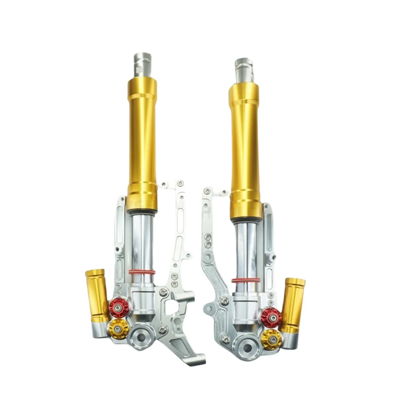
- Fit and torque checks: verify fastener access and torque values; record oil type/viscosity and bleed steps; confirm clearances on the target chassis.
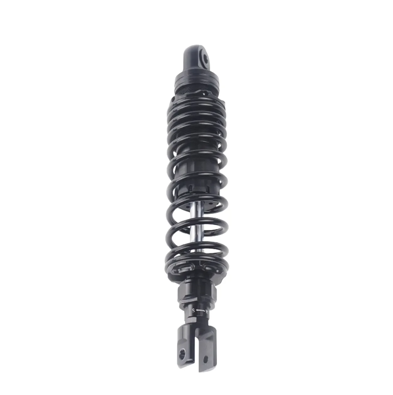
- Aesthetic checks: compare prototype anodize against the master; inspect engraving alignment and legibility; document packaging mockups. For product context on shock families and validation scope, you can review a typical rear shock program here: Rear shock absorbers context.
Here’s the deal: if you standardize test temperatures, dyno nodes, and torque discipline now, you prevent weeks of debate later.
Parallel tooling and fixtures
Weeks 4–7 overlap with prototyping to protect the schedule. While tuning the prototype, the tooling team designs fixtures, engraving setups, and anodizing racks.
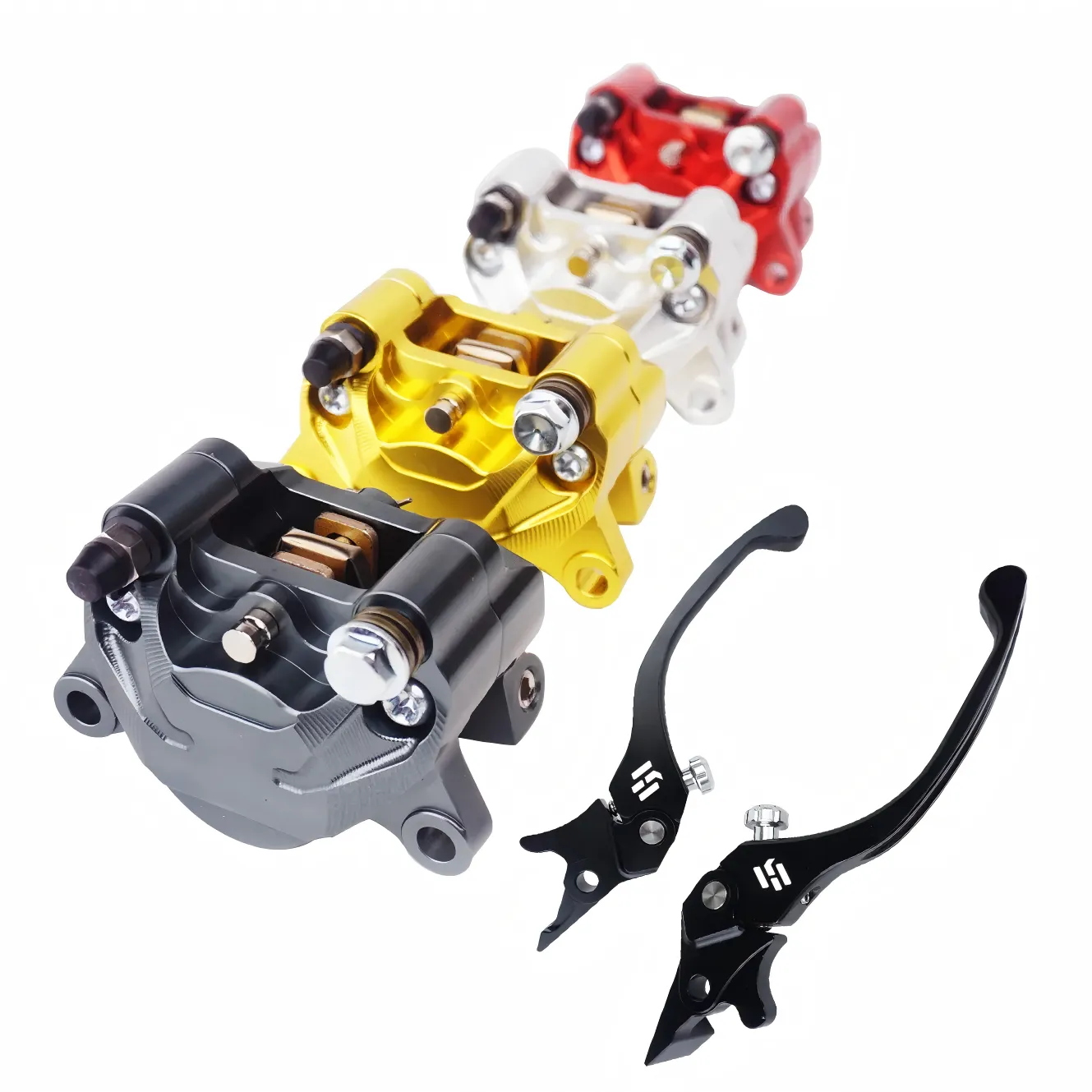
- Modular inserts enable three color variants and different laser graphics without restarting the tooling queue.
- Anodizing rack strategy—consistent part orientation and spacing—reduces color variance and shadowing.
- A tooling acceptance checklist should cover cavity identification, dimensional capability plans on key features, cosmetic gate locations, and a pilot trial plan.
This is where motorcycle suspension OEM/ODM development gains speed: parallelizing tooling with late‑stage prototype tuning, provided CTQs and gates are crystal clear.
Pilot run, FAI, and capability snapshot
Weeks 7–9 validate the manufacturing process with a small pilot batch.
- First Article Inspection: run a full dimensional layout on a representative sample; confirm torque specs and stroke; capture dyno spot‑checks against the bands established earlier.
- Aesthetic confirmation: measure color against the master using visual assessment plus Lab* instrumentation; verify engraving alignment using dedicated fixtures.
- Capability snapshot: for one or two CTQs (e.g., stroke), produce an initial process study to show stability; keep this pragmatic in aftermarket volumes. When you reference capability studies and process control in formal terms, the AIAG Quality Core Tools provide the model and shared language across suppliers and buyers; see the overview here: AIAG Quality Core Tools hub.
PPAP‑equivalent package in motorcycle suspension OEM/ODM development
Weeks 9–11 assemble a right‑sized approval bundle. While “PPAP” belongs to automotive OEMs, private‑label buyers benefit from the same discipline: a signed declaration, traceable design records, dimensional and performance evidence, and a Control Plan that shows how CTQs will be held in production.
A practical list, aligned to common industry explainers and anchored by AIAG’s formal model, includes:
- A signed part submission declaration (PSW‑style) stating conformance to agreed specs
- Design records and any drawings you own
- Dimensional results on agreed characteristics and materials certs
- Process flow, PFMEA, and Control Plan excerpts for CTQs
- Initial process studies for selected CTQs and an Appearance Approval Report for cosmetics
- Sample parts and a master sample retained for reference
For a business‑friendly overview of PPAP elements and submission levels, see this explainer: Fictiv’s PPAP overview. If you need a formal reference for level definitions and PSW handling in an OEM context, review the Ford Customer‑Specific Requirements for PPAP, which illustrates how a major OEM frames submissions and approvals: Ford PPAP Customer‑Specific Requirements, Jan 2025.
SOP, change control, and spare parts plan
Week 12 is Start of Production. The output is more than a green light; it’s a documented way of building the part the same way every time.
- Work instructions: oil fill and bleed steps with photos, torque sequences, cleanliness controls, engraving setup, and packaging assembly.
- Training and qualification: certify operators on critical tasks; maintain calibration on dyno and torque tools; complete measurement systems analysis for variable gauges so capability charts aren’t garbage in, garbage out.
- Control and monitoring: SPC for stroke and force at defined nodes where practical; traceability and labeling; a change control workflow that routes any design or process change back through risk review and sign‑off.
- Spare parts policy: define wear‑part availability and labeling to support aftermarket service centers and reduce returns.
Case notes and a practical example
Disclosure: Kingham Tech is our product.
In a recent motorcycle suspension OEM/ODM development program for a three‑variant rear shock, an end‑to‑end partner like Kingham Tech can compress the calendar by parallelizing activities. For example, while prototype two is running dyno repeats and fit checks, the tooling team finalizes engraving fixtures and anodizing racks, using pre‑approved color libraries to hold ΔE within the agreed window. That combination safeguards the “feel” gate and the visual gate at the same time. If you want to see what an end‑to‑end manufacturing stack looks like—CNC capacity, in‑house anodizing, and quality discipline—browse this context page: Factory tour and in‑house capabilities. The same discipline underpins the Control Plan that becomes your SOP.
Next steps
If you’re preparing a brief, gather platform fitment details, rider profiles, damping targets, and three visual references per colorway, then agree CTQs and acceptance bands up front. Ask your supplier to propose a gate map with deliverables and a PPAP‑equivalent checklist scaled to your volume. To start a structured conversation with clear milestones and aesthetic options, visit the OEM/ODM overview: Expert motorcycle suspension OEM/ODM partner.
One‑page view of inputs and outputs by phase
| Phase and weeks | Your inputs | Supplier outputs |
|---|---|---|
| Brief → CTQs (0–1) | Fitment, rider/use cases, feel targets, adjustability, colorways, engraving, packaging, MOQs | Requirements matrix, CTQs, gate criteria, master samples plan with visual + Lab* checks |
| Concept and DFM (1–3) | Feedback on CAD appearance and packaging | Concept CAD, DFM notes, preliminary PFMEA, finish options and controls |
| Prototypes and tests (3–6) | Approve dyno bands, confirm fit priorities | Prototype samples, dyno curves and reports, torque and dimensional records, aesthetic mockups |
| Parallel tooling and fixtures (4–7) | Approve engraving graphics and color references | Tool and fixture designs, anodizing rack plan, tooling acceptance checklist |
| Pilot and FAI (7–9) | Pilot approval criteria | FAI report, aesthetic confirmation with ΔE data, capability snapshot on selected CTQs |
| PPAP‑equivalent (9–11) | Sign‑off reviewers and format | PSW‑style declaration, design and dimensional records, PFMEA/Control Plan excerpts, initial studies, master sample |
| SOP and launch (12) | Shipping marks and labeling preferences | Operator work instructions, training records, SPC plan, traceability, change control and spare parts policy |
References and formal models
- APQP, PPAP, FMEA, MSA, and SPC are standardized quality tools in automotive; for definitions and training overviews refer to the authoritative summary here: AIAG Quality Core Tools hub.
- For OEM submission levels, PSW handling, and approval nuances in a formal context, see this example of customer‑specific requirements: Ford PPAP Customer‑Specific Requirements, Jan 2025.
- For how appearance is evaluated on anodized aluminum parts in practice, including the role of visual assessment and ΔE, consult: QUALANOD appearance guidance.
- For a business‑friendly explainer of PPAP elements and levels, see: Fictiv’s PPAP overview.
SEO note for readers searching this topic: this case focuses on motorcycle suspension OEM/ODM development and how parallelized gating, right‑sized PPAP‑equivalent packages, and disciplined SOPs get your private‑label shock from brief to shipment on a tight, predictable timeline.